Ignition systems and alternators
for oldtimer motorcycles
34 years of VAPE anniversary
Through purposeful efforts and constant large investments, we managed to build a successful and prosperous company of European format. Hereby we want to thank you that you too have contributed to the positive development of our company.
Our production program
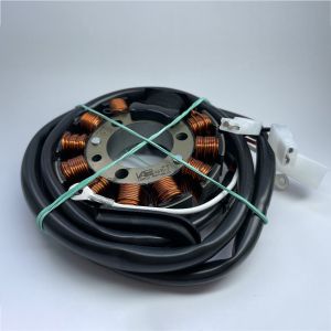
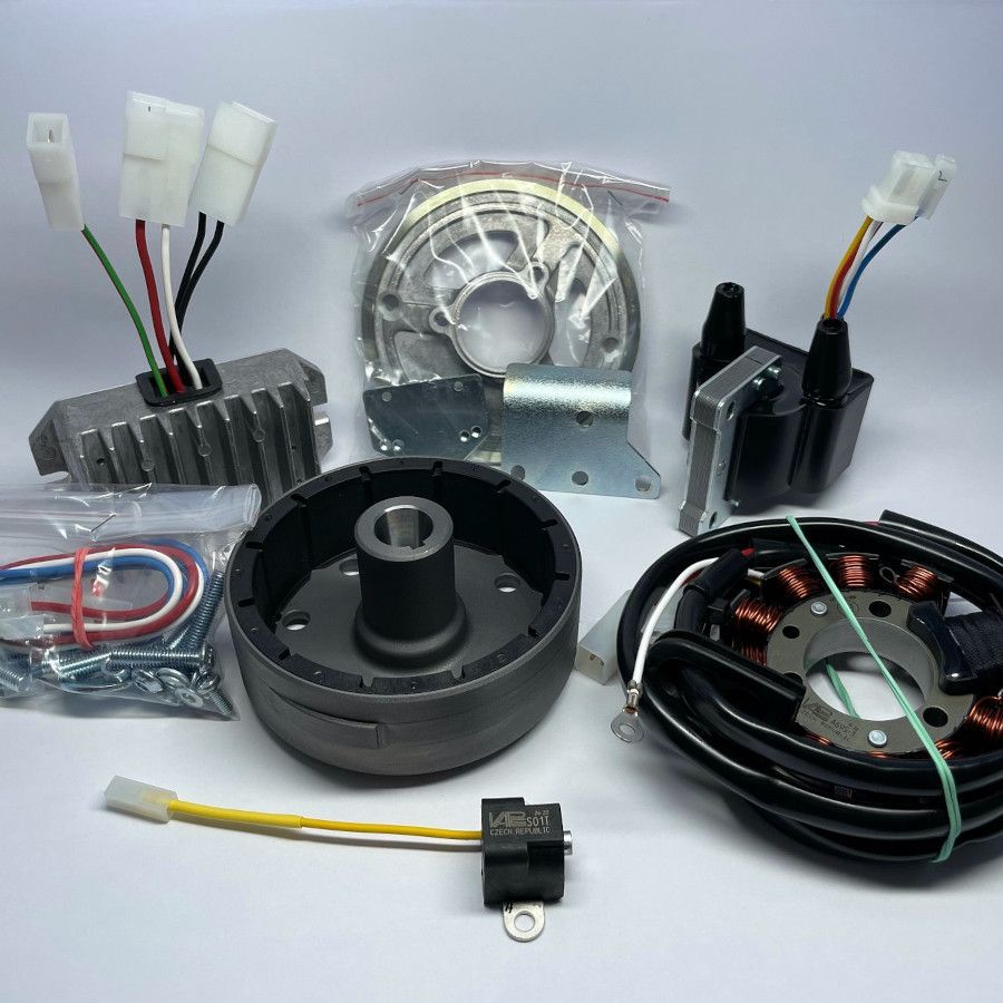
The alternator assembly consists of rotor and stator. It produces electric current for power supply for igniton and electrical appliances on the vehicle.
Rotors
Type designation: AR.. (+1 to 2)
Rotor is a rotating part of alternator. It consist of the magnetically conducting mantle shell in the form of " U". The mantle is symmetric riveted on the nave of rotor (carrier of the rotor). Inside on the mantle circumference are fixed the permanent magnets. On the rotors with the external sensing is on the mantle circumference forced or fixed the pole shoe , further only "mark". It means the magnetically conducting stump around 2 mm over the mantle circumference. The mark on the rotor has according to the purpose diverse shape and legth. The nave of rotor has in its axis a conical opening, through which is the whole rotor drived on the crank of motor.
Function of rotor
It is concerned the rotors of alternators with permanent excitation, where the magnetically flow is not excited of the battery, but it is excited through the permanent magnets. The magnetical flow is closed from the magnets through the stator core and rotor mantle. At the rotation of the rotor is induced the electric current in the windings of the stator of alternator. The types of the windings are described in part STATORS. The mark is only on the rotors with "external sensing ", in the sets, where is the synchronizing electric impuls obtained through position sensor. At the rotation of rotor pass the mark at close quarters position sensor, in which induces the electric impuls for ignition control. Angular position of the mark is exactly defined compared to skewing of the crankshaft. Generally is the position of rotor and thereby also of the mark fixed through the key over the groove in the rotor nave and crankshaft.
Disposal of rotors:
- According to the diameter
- Ø 112 mm
- Ø 103 mm
- According to the synchronizing principle:
- for external sensing, has the rotor on the circumference 1 to 2 marks, depending if it is for 1 cylinder or 2 cylinder engine. For the direct control of the electronic ignition switches it concerns about angular short marks, eventually marks with gradual incidence over the reverse running of motor.
The marks for the control of the digital control unit have a longer mark, around 28°. - for internal sensing are the rotors modified so, that always one magnet is not magnetized
- for external sensing, has the rotor on the circumference 1 to 2 marks, depending if it is for 1 cylinder or 2 cylinder engine. For the direct control of the electronic ignition switches it concerns about angular short marks, eventually marks with gradual incidence over the reverse running of motor.
- According to the type and length of rotor nave, according to the coning angle and input diameter of conus opening.
- Disposal according to the electric output of alternator is described in part STATORS.
Important warning!
At the manipulation it is non-permissible the mechanical straining of the mantel circumference of the rotor or fall of rotor on the cant of mantel circumference. Also is non-permissible the direct mechanical straining of the magnets. At that manipulation it could come to the damage of magnets.
Stators
Type designation: AS.. (+1 to 2)
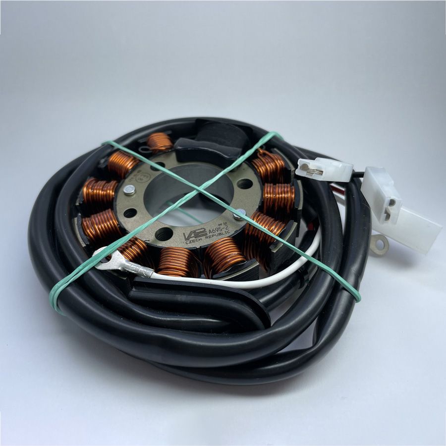
Stator is a static part of alternator. It consist of a magnetically conducting core starform, at what are cyclic fixed the winding coils. By rotation of the external rotor with the permanent magnets is induced into the winding the electric current for the power supply of the ignition and the electric appliances in the board net.
According to the purpose we differ on the stators three types of electric winding:
- Source winding for the power supply of the electric appliances of the voltage rating 12V or 6V.
The winding is wound with a isolated wire of a bigger diameter. - Charging winding for power supply of the ignition.
Output voltage is pulse. The value depends on the turning speed of the rotor and it variates from 80V to 400V. The electric resistance is approximately about 550 to 630 ohm. Winding is wound on a bigger black plastic coil frame. For the two-cylinder engines are two coil like this placed together after 180°. - Synchronizing winding is used at stators in sets, which do not use for the control of ignition the position sensor. In the winding are induced the voltage impulses, whose frequence is identical with the frequence of the crank movement of the engine. For 1 crank revolution 1 impuls. The electric impulses are used for the control of the ignition. Either directly to the control of the el. switch, or for the control of the digital control units at the sets with the regulation of preignition charakteristic of ignition.
The winding is wound on the two small black coils, whose el. resistance is 70 to 75 ohm.
Disposal of stators:
- According to the type of synchronizing of ignition (external or internal sensing).
- in the set is used the external sensor of rotor position:
The stator has not a synchronizing winding. It contains only charging and source winding. For the two cylinder engines are the charging winding two. (on two big black coils). - in the set is not used the external sensor of rotor position:
The stator has a synchronizing winding (it is wound on two small black coils). Further it contains the charging coil and source winding.
- in the set is used the external sensor of rotor position:
- According to the sense of rotation of rotor / running direction
- "righthanded" stators
- "lefthanded" stators
- According to the electric output [W].
- Standard type according to the combination with the rotor
- with rotor Ø 112 mm, without the synchronizing coils 185 W
- with rotor Ø 112 mm, with the synchronizing coils 140 W
- with rotor Ø 103 mm, without the synchronizing coils 140 W
- with rotor Ø 103 mm, with the synchronizing coils 100 W
- The special design has a combined source winding. A part of the winding supplies after rectification only the battery and some appliances, e.g. stop light, direction indicator etc. The second part of winding with major el. output supplies the bulbs for the lighting with alternating current.
- Standard type according to the combination with the rotor
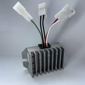
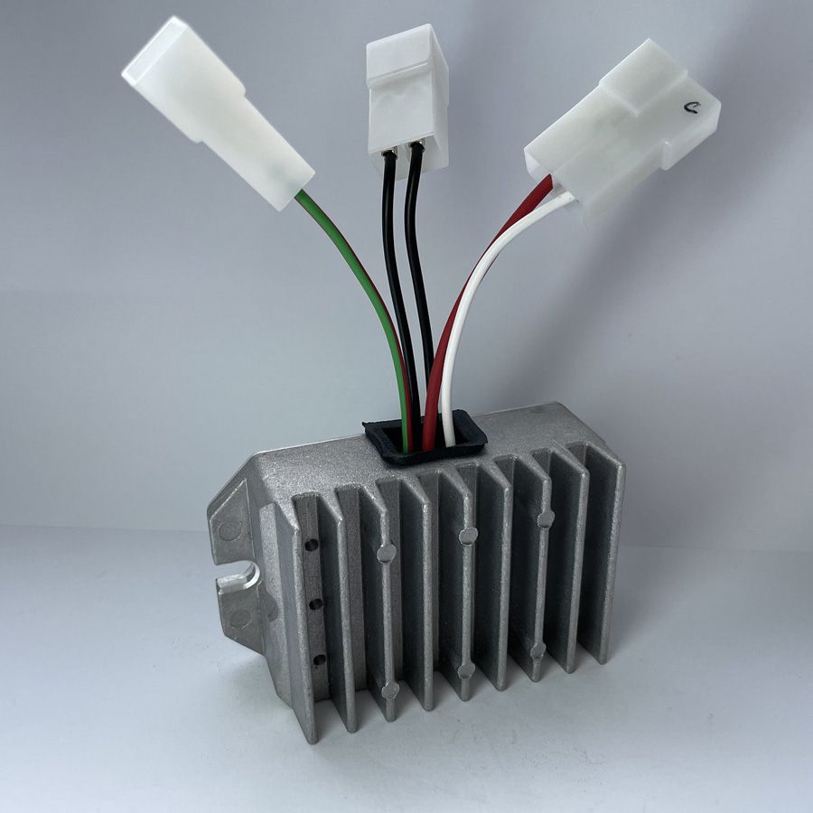
Voltage regulators regulates electric voltage from the alternator so, that it could not come to the damage of the electrical appliances, eventually battery overcharge.
Voltage regulators, further only Regulators
Type designation: R..(plus 2 numbers)
Functional description of voltage regulator:
The voltage regulator is a electronic equipment, which regulates the electric voltage generated by the alternator or dynamo at range from 14V to 14,4V for voltage rating board net 12V and from 7 to 7,2V for voltage rating board net 6V
Regulated voltage in the mentioned range provides the correct function of battery and protection of appliances befor destruction. The precondition of the correct function is, that it mustn´t come about the electric power overloading of regulator. E.g.: Regulator has max. el. power 200W. It means, the power of alternator must be Palt <= 200W. Further the sum of the electric input of the appliances in the board net mustn´t be greater than 200W.
By overloading it could come about the destruction of the regulator or battery discharge and destruction.
RRegulator for the alternating voltage ensures average value of voltage in the mentioned range. It means, that e.g. with the oscilloscope measured voltage varies periodically to the higher values than the rated value is. E.g. +- 20V to 30V. Average value ensures again, that the appliances type the el. bulb will be not destroy. It holds there also the rule, that the sum of el. input of the appliances must be Ps[w] Ł= Preg[W]. It means, that the regulator must be chosen according to rated voltage [V] and max. electric input [W].
Rectifier
Rectifier It consist of the power diodes filed into the rectifier bridge (full wave) or set (half-wave). It rectifies the alternating el.current from the alternator. On the output from the rectifier is already pulse direct current, whose wave dwindles through the attached battery.
Disposal of regulators
- According to the content of units in one cover
- only voltage regulator
- voltage regulator incl.rectifier of the el.current
- combined regulator for alternating el. voltage and direct el. voltage with rectifier
- According to the rated voltage in board net and form of voltage
- rated voltage 6V or 12V
- alternating or direct voltage
- According to the electric power output (loading) of regulator
Important warning !
By the connection of the regulator into the electric net it mustn´t come about the replacement between + and - battery. It comes so about the destruction of the regulator.
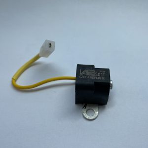
Sensor of rotor position - further only sensor
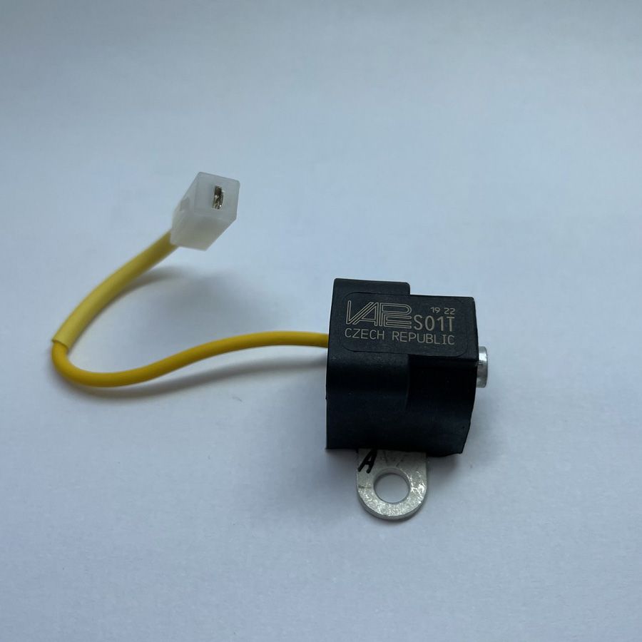
Type designation: S0..(+ 1 number and one mark)
Description of sensor assembly:
It is concerned the electric appliance, which contains:
- support for mechanical fixation of magnetically conducting material
- magnetically conducting core, on which is put the sensor coil. The core extrudes on one side and creates the pole adapter
- permanent magnet, which is by one pole conductive connected with the support and by second pole with the coil core
- electrical output with connector
The whole sensor assembly is splashed into the plastic.
Functional description sensor:
he princip is based upon the magnetoelectric induction. Through the swift motion of the magneticall conducting material e.g. iron (Fe) near the pole output of coil core rises the change of the magnetic flow. The magnetic flow is closed from the magnet through coil core over the leak into the support on the second magnet pole. Magnetic flow carrying through the core induces in the coil windings the electrical impuls of both polarities. In the ignition set rotates the stump on the alternator rotor in the spacing cca 0,5 mm above pole of sensor core. The induced electrical impuls of the sensor is reduced on the input of electronic ignition coil or digital control unit of ignition, where it is regulated and formed. Basically the sensor ensures the information about the angular position of the crankshaft and synchronizes the electric spark on the spark plugs with the crankshaft revolution and piston position.
Using and disposal of sensors:
Sensor is constructed universal, to comply with its construction in all varieties of VAPE ignition sets with external sensing. It shares according to the type of connector on the output and magnetical polarity on core pole. The electric resistance of sensor coil is approximately 210 ohm. It is measured between the tag and sensor support.
Attention!
The sensor support has to be electrically connected with the support of ignition coil or with earthe-wire of digital control unit of ignition on the vehicle.
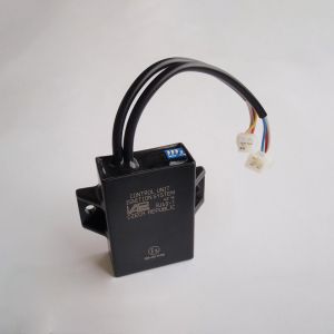
Digital control unit is a digital memory system , which controls the value of advance ignition of gas mixture in engine.
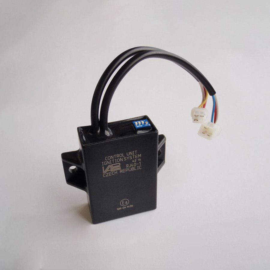
Digital control unit , further only control unit
Type designation: RJ.. (plus 2 numbers)
Functional description of control unit:
It is a digital memory control system, which controls the value of the preignition of the gas mixture depending on the engine rpm . It is concerned a modification of the angular value < ![]() before the TDC of the engine crankshaft according to the predefined characteristics. Into one control unit it is possible to pre-set also more characteristics , by request of the customer, eventually to control the preignition by yet another parameter, than the engine rpm. E.g. by means of the dependance on the cold and hot engine or the dependance on the value of the underpressure in the suction tube etc.
before the TDC of the engine crankshaft according to the predefined characteristics. Into one control unit it is possible to pre-set also more characteristics , by request of the customer, eventually to control the preignition by yet another parameter, than the engine rpm. E.g. by means of the dependance on the cold and hot engine or the dependance on the value of the underpressure in the suction tube etc.
Digital units works in the electric connection with various VAPE ignition systems.
Disposal of control units
- According to control signal mode/type
- The control signal is reduced from the sensor (so-called external sensing). The sensor is placed in the place above the perimeter of rotor of alternator. On the rotor is a metal stump , which rotates nearly sensor and induces the electric voltage in it .
- The control signal is reduced into the control unit directly from the synchronizing coils of the stator of alternator (so-called internal sensing). This mode does not require external sensors .
- According to ignition type
- battery (inductive)
- condenser- (capacitive)
- According to power supply
- from the battery circuit
- independent /power/ supply (autonomic)
- According to range of working speed/ engine rpm
- 60 till 10 000 min -1
- 100 till 15 000 min -1
- 300 till 24 000 min -1

